Quantcast
Channel: pfSense Setup HQ » load-balancing
Viewing all 11 articles
Browse latest View live

pfSense Virtual IP Addresses: Part One

$
0
0
pfSense Virtual IP Addresses

Virtual IP address configuration page in pfSense.

A virtual IP address (VIP or VIPA) is an IP address that is not assigned to a specific single server or network interface card (NIC). Rather, it is assigned to multiple applications on a single server, multiple domain names, or multiple servers. Normally, a server IP address depends on the MAC address of the attached NIC, and only one logical IP may be assigned per card. However, VIP addressing enables hosting for several different applications and virtual appliances on a server with only one logical IP address. VIPs have several variations and implementations, including Common Address Redundancy Protocol (CARP) and Proxy Address Resolution Protocol (Proxy ARP).

pfSense Virtual IP Addresses: Proxy ARP

pfSense allows four types of virtual IP addresses: Proxy ARP, CARP, Other, and IP Alias. In this article, I will cover how to configure pfSense virtual IP addresses using Proxy ARP and CARP.


The different types of virtual IP addresses have slightly varied properties. With proxy ARP, the properties are:

  • Can only be forwarded by the firewall (cannot be used by the firewall)
  • Uses Layer 2 (the data link layer) traffic
  • Can be in a different subnet than the interface
  • Cannot respond to pings
pfSense Virtual IP Addresses

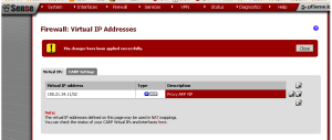
Once the Virtual IP has been entered and saved, it is added to the list.

To configure a Proxy ARP virtual IP address, browse to Firewall -> Virtual IPs and Click the “plus” button to add a new virtual IP address. At type, there are four radio buttons; select the radio button for “Proxy ARP” (it should be the default selection). For “Interface”, select “WAN”. At “IP Address(es)“, select “Single address” for “Type” (this should be the default). At “Address“, specify an IP address. At “Description“, enter a description if desired. Then press “Save” to save the changes and “Apply changes” to apply changes if necessary.

Now, the newly-created VIP should be listed at the “Virtual IPs” tab at Firewall -> Virtual IPs.

pfSense Virtual IP Addresses: CARP

You can also configure a virtual IP with CARP in pfSense 2.0. The properties for a CARP VIP include:

  • Can be used or forwarded by the firewall
  • Uses Layer 2 (data link layer) traffic
  • Should be used in firewall fail-over or load-balancing scenarios
  • Must be in the same subnet as the interface
  • Will respond to pings if configured properly

To set up a CARP virtual IP address, browse to Firewall -> Virtual IPs and click the “plus” button to add a new virtual IP address. At “Type“, select the “CARP” radio button, and at “Interface“, select “WAN” (it should be the default). At “IP address(es)“, specify an IP address. At “Virtual IP Password“, specify a password. At “VHID Group“, choose a group. At “Advertising Frequency“, select a frequency (0 for master). At “Description“, add a description if desired. Then press “Save” to save the changes and “Apply changes” to apply the changes if necessary.

In part two of this series, I will cover setting up virtual IP addresses with IP Alias and Other types.

Once again, the “Virtual IPs” tab under Firewall -> Virtual IPs should display the newly-created VIP within the list of pfSense virtual IP addresses. In part two, I will cover IP aliases (new to pfSense 2.0) and other VIPs.


External Links:

What are Virtual IP Addresses? at doc.pfsense.org

The post pfSense Virtual IP Addresses: Part One appeared first on pfSense Setup HQ.


pfSense Load Balancing: Part One

$
0
0
pfSense Load Balancing

Configuring OPT1 as WAN2 so we can set up a gateway group later on.

In computer networking, load balancing is a method for distributing workloads across multiple computers or a computer cluster, network links, CPUs, storage devices, or other resources. When load balancing is employed, we are looking not just to distribute workloads but to optimize resource use, maximize throughput, minimize response time, and avoid overhead. Using multiple components with load balancing instead of a single company can also increase reliability through redundancy. Load balancing has implicit failover capabilities, since load balancing software is capable of detecting when a resource (e.g. network interface, hard drive) is down and excludes it from the group. Load balancing is usually provided by dedicated software or hardware, such as a multilayer switch or a Domain Name System process, or, as we shall soon see, through pfSense. In this article, I will begin our look at pfSense load balancing.


pfSense Load Balancing: Gateway Configuration

As an example, let’s assume we want to set up multiple WAN interfaces and use load balancing on the group. A default WAN gateway was already created when pfSense was set up. In this example, we will use OPT1 as an additional gateway, and then add both the default interface and OPT1 to a newly-created gateway group, which will employ pfSense load balancing to distribute the workload in round-robin fashion.

The first part of our configuration follows the steps outlined in my <a href=”http://pfsensesetup.com/pfsense-gateways/”>article on gateways</a>. In order to set up our second gateway, first browse to System -> Routing. Click on the “Gateway” tab, if it is not already selected. Click on the “plus” button to add a new gateway. At “Interface”, select OPT1 in the drop-down box. At “Name”, type a name, such as “WAN2″. At “Gateway”, type in the IP address of the network interface (in this case, 192.168.3.1). Check “Default Gateway”, and at “Description”, add a description. Then press the “Save” button to save changes, and, if necessary, press the “Apply changes” button on the next screen.


Next, we will make some changes to the WAN interface (the one described as “Interface WAN Dynamic Gateway”). From the Gateways tab, click on the “edit” button. We can leave “Interface and Name” unchanged, but at “Gateway” we will type an IP address (in this case, 192.168.3.11). Click on “Default Gateway” and change the description to something appropriate (e.g. “WAN gateway). Then press the “Save” button to save the changes, and press the “Apply Changes” button if necessary.

Now we have the two interfaces configured correctly. In part two of this series on pfSense load balancing, we will take our newly-configured WAN interfaces and add them to a gateway group, and configure load balancing for the group.

Erratum: The Original Instructions I Posted Contained an Error, and Here’s Why

It occurred to me when composing Part Two of this article that I made a mistake. I set the WAN gateway to 192.168.4.1 originally; however, since WAN2 is on the 192.168.3.0 subnet, and both WAN gateways will likely be connecting to the same network, they should be on the same subnet. Therefore, I amended the instructions for Part One so that WAN is set to 192.168.3.11. I apologize for any confusion I may have caused.

Other Articles in This Series

pfSense Load Balancing: Part Two

pfSense Load Balancing: Part Three (Web Server Failover)

External Links:

Load Balancing at Wikipedia

Setup Incoming pfSense Load Balancing at doc.pfsense.org

Multi-WAN Load Balancing at pfsensesolution.blogspot.com

The post pfSense Load Balancing: Part One appeared first on pfSense Setup HQ.

pfSense Load Balancing: Part Two

$
0
0

In part one on my series on pfSense load balancing, we configured the two WAN gateways. In part two of this series on pfSense load balancing, we will set up a load balanced gateway group.

pfSense Load Balancing: Configuring Interfaces for MultiWAN

pfSense Load Balancing

Configuring the WAN interface.

First, we must configure the interfaces. Navigate to Interfaces -> WAN. and click on “Enable Interface” if it is not already checked. At “Type“, change the interface type to “Static“. At “Static IP Configuration“, type in an IP address (in this case, 192.168.3.12). Select “24” in the drop-down box next to the IP address edit box, to indicate the proper network prefix. This is important, because if the network prefix is not set, we will not be able to enter a monitor IP address later on. At “Gateway“, specify the WAN gateway (192.168.3.11). Set Leave “Block private networks” and “Block bogon networks” checked. Press the “Save” button to save the changes and on the next page press “Apply changes” if necessary.


Now the OPT1 interface must be configured. Navigate to Interfaces -> OPT1 and click on “Enable Interface”. At “Type“, change the interface type to “Static“. At “Static IP Configuration”, type in an IP address (in this case, 192.168.3.2). Again, select “24” in the drop-down box to indicate the network prefix. At “Gateway“, specify the WAN gateway (192.168.3.1).Again, leave “Block private networks” and “Block bogon networks” checked. Press the “Save” button to save the changes and on the next page press “Apply changes” if necessary.

pfSense Load Balancing: Creating the Gateway Group

pfSense Load Balancing

Adding a gateway group in pfSense 2.0.

Now that both interfaces are configured, we can create the gateway group. Navigate to System -> Routing and click on the “Groups” tab. At “Group Name”, enter a name (e.g., “MultiWAN”). At “Gateway Priority“, set both WAN and WAN2 to “Tier 1″. Leave the “Trigger Level” at “Member Down”, and at “Description“, enter a description (e.g., “WAN gateway group”).Press the “Save” button to save the changes and on the next page press “Apply changes” if necessary.


Before we go any further, we may want to enter a Monitor IP. Click on the “Gateways” tab at System -> Routing and click on the “edit” button for WAN. At “Monitor IP“, enter an alternative monitor IP or domain name (I opted for Google, so I entered Google’s IP, 173.194.43.33). Once this is done, click the “Save” button to save changes. Repeat this procedure for the WAN2 interface (it would be prudent to choose a different monitor IP, so that a failure of the host selected for the monitor IP does not result in pfSense thinking both gateways are down). Once you have pressed the “Save” button on the WAN2 configuration page, press “Apply Changes” on the next page if necessary.

pfSense Load Balancing: Adding a Firewall Rule

Now all that is left to do is to configure a firewall rule. Navigate to Firewall -> Rules and click the “plus” button to create a new firewall rule. At “Action“, select “pass” in the drop-down box. At “Interface“, be sure to select the LAN interface. At “Protocol“, set the protocol to “any”. At “Source“, set the source to “any”, and at “Destination”, set the destination to any. At “Description“, add a description. Scroll down to “Advanced features” and press the “Advanced” button next to “Gateway“. Select “MultiWAN” as the gateway. Then press “Save” to save the changes and on the next page, press “Apply Changes” if necessary.

Now, all traffic from our LAN will go through the gateway group. Since the gateway group consists of two WAN gateways on the same level of priority, traffic will alternate back and forth in round-robin fashion. Also, because each gateway within the group is monitoring an external IP address, pfSense will know when a gateway is down and exclude that member from the group.

Other Articles in This Series:

pfSense Load Balancing: Part One

pfSense Load Balancing: Part Three (Web Server Failover)

External Links:

Configure Load Balancing on Your Site Using the pfSense Firewall

The post pfSense Load Balancing: Part Two appeared first on pfSense Setup HQ.

pfSense Load Balancing: Part Three (Web Server Failover)

$
0
0

In parts one and two of this series, I demonstrated how to configure a gateway group for the WAN gateway. In this article, I will cover setting up a cluster for web server failover using pfSense load balancing.

Web Server Failover, Step One: Add the Monitor

Web Server Failover

Setting up the monitor for our web server failover.

First, navigate to Services -> Load Balancer and click on the “Monitors” tab. Here you will see several predefined entries: ICMP (Internet Control Message Protocol), TCP, HTTPS, and SMTP (Simple Mail Transfer Protocol). Click the “plus” button to add a new entry. At “Name“, specify a name, and at “Description“, enter an appropriate description. At “Type“, set the type to HTTP, and set the “Host” to the IP address of the primary web server. Leave “Path” unchanged, and at “HTTP Code“, leave the code as “200 OK”. Press the “Save” button to save changes and on the next screen, press “Apply changes” if necessary.

Web Server Failover, Step Two: Add the Web Server Pool

Web Server Failover

Setting up a simple pool with a primary and backup web server.

Next, click on the “Pools” tab. Click the “plus” button to add a new pool. At “Name“, specify an appropriate name, and at “Mode“, set the mode to “Manual Failover“. At “Description“, add an appropriate description. Since this is a web server failover pool, at “Port” enter 80. You can leave “Retry” blank, or optionally set the number of retries. Under “Add Item to Pool“, set “Monitor” to whatever you named the monitor as in the previous step (in my case “WebsiteFailover“). At “Server IP Address“, add the IP address of the primary web server and click the “Add to pool” button. Then add the IP address of the backup web server and click the “Add to pool” button. The backup server will show up in the “Pool Disabled” text box. Then press the “Save” button to save the changes and press the “Apply changes” button if necessary on the next page.


Web Server Failover, Step Three: Add the Virtual Server

Next, click the “Virtual Servers” tab and click the “plus” button to add a new virtual server. At “Name“, specify an appropriate name and at “Description“, add a description. At “IP address“, set the appropriate address (most likely this will be the WAN IP, so I typed 192.168.3.1 here). At “Port“, type 80, since this is for web server failover. “At Virtual Server Port“, select the web server pool created in the previous step. Leave “Fail Back Pool” unchanged (none) and leave “Relay Protocol” unchanged (tcp). Press the “Submit” button to submit changes and “Apply changes” on the next page if necessary.

Web Server Failover, Step Four: Add the Firewall Rule

Web Server Failover

Adding a firewall rule to allow traffic to pass through to the web servers.

Finally, we must create a firewall rule for the newly-created virtual server. It would be handy to create a an alias for both the primary and backup web server, so first navigate to Firewall -> Aliases. At “Name” enter a name (I chose “VirtualApache”), and at “Description“, enter a description. Leave “Type” unchanged, and at “Hosts“, enter the IP addresses of both the primary and backup web servers (in my example, 192.168.3.20 and 192.168.3.21). Then press the “Save” button to save, and “Apply changes” if necessary.


Navigate to Firewall -> Rules and click the plus button to create a new firewall rule. As “Action“, select “pass” in the drop-down box. At “Interface“, select “WAN” or whatever is being used as the WAN gateway. At “Protocol“, leave the protocol as “TCP”. At “Source“, leave the “Type” as “any” and click on the “Advanced” button to show the source port range. Select “any” in the drop-down box and type 80 in the top edit box (alternatively, you could select “HTTP” in the drop-down box). At “Destination“, select “Single host or alias” as the “Type“, and at “Address” type the alias you defined above (in my case, VirtualApache). You do not need to specify a “Destination port range” and you should probably leave “Log packets that are handled by the rule” unchecked. At “Description“, enter an appropriate description and click the “Save” button. If necessary, click “Apply changes” on the next page. If you want to pass HTTP Secure (HTTPS) traffic, then you will need to create an additional rule. If so, then follow the steps outlined above, but for the source port range, type 443 or select “HTTPS” in the drop-down box.

Conclusion

Now that configuration is complete, pfSense is set up to automatically redirect traffic from the primary web server to the backup web server in the event of a failure. The pool defines the location of the web servers and the failover mode. The virtual server defines the IP addresses used in the NAT and firewall rules to listen for HTTP traffic, which the virtual server redirects to the pool. The monitor will check on the status of the primary web server by periodically making a web request. If it gets back a “200 OK” code, then the pool will send traffic to the primary server; otherwise, it will send traffic to the backup.

Other Articles in This Series:

pfSense Load Balancing: Part Three (Web Server Failover)

pfSense Load Balancing: Part Two

External Links:

Inbound Load Balancing at doc.pfsense.org”>

pfSense Load Balance Fail-Over Setup

Load Balance and Cluster Failover Webserver (includes how to set up and install pfSense)

How to Use pfSense to Load Balance Your Web Servers


The post pfSense Load Balancing: Part Three (Web Server Failover) appeared first on pfSense Setup HQ.

Advanced Miscellaneous Settings in pfSense

$
0
0

In this article, I will cover some of the Advanced Miscellaneous settings for pfSense. These settings can be found by navigating to System -> Advanced and clicking on the “Miscellaneous” tab.

Advanced Miscellaneous Settings: Proxy Support, Load Balancing, and Power Savings

Advanced Miscellaneous

Some of the Advanced Miscellaneous settings in pfSense.

The first heading in Advanced Miscellaneous settings  is “Proxy Support”. These settings allow you to configure an external web proxy, rather than add a web proxy such as Squid to pfSense. The first option is “Proxy URL“. In this edit box, specify the URL or IP address of the proxy. Next is “Proxy Port“, which specifies the port to use to connect to the proxy (the default is 8080 for HTTP, or 443 for SSL). Then there is “Proxy Username” and “Proxy Pass“, the username and password for the proxy server.

The next heading in Advanced Miscellaneous settings is “Load Balancing”. I already covered load balancing in a series of previous articles (part one part two part three), so I will keep this brief, but I will note that there are two important settings pertaining to load balancing here. The first is the “Use sticky connections” check box. This setting applies in cases where you have a pool with multiple servers with load balancing enabled. Typically, when load balancing is invoked, successive connections are redirected to the servers in a round-robin fashion, and we don’t care if successive connections from the same source are redirected to different servers. Sometimes we do care, however, and in those cases we can check this check box. If this box is checked, successive connections from the same source will be sent to the same web server. This is referred to as a “sticky connection”, and it will exist as long as there are states in the state table that refer to the connection. Once the states expire, so will the sticky connection, and further connections from that host will be redirected to the next server in the round robin pool.

The second check box is “Allow default gateway switching“. If this box is checked, then if the default gateway fails, it will be switched to another available one. This is useful if you have a multi-WAN setup. If the default gateway fails, outbound traffic will be directed to another gateway (e.g. WAN2), and you will still be able to access the internet. If you do not have this box checked, however, even if you have a multi-WAN setup, if the default gateway fails you will lose internet.


The next heading in Advanced Miscellaneous settings is “Power savings”. Here you will find the “Use PowerD” check box. Checking this box invokes the powerd utility, which monitors the system state and sets various power control options accordingly. There are three modes for powerd: maximum, minimum, and adaptive. Maximum mode chooses the highest performance values; minimum mode selects the lowest performance values (which in turns yields the greatest power savings). Adaptive mode attempts to strike a balance between these two settings by degrading performance when the system appears idle and increasing it when the system is busy. Checking this box will invoke powerd in adaptive mode, if nothing else is changed. There is no way to change the mode to min or max from the GUI (yet). If you want to change the mode, however, you can always edit /etc/inc/system.inc manually. In order to do so, log into your pfSense box via SSH, open up system.inc in vi like so:

vi /etc/inc/system.inc

and look for the function activate_powerd(). You shouldn’t have to scroll down very far. Look for the following line to edit:

exec(“/usr/sbin/powerd -b adp -a adp”);

the “-b” parameter is for battery and “-a” is for A/C. “adp”, of course, is short for “adaptive”. Chnage these parameters to either “min” for minimum mode or “max” for maximum mode as you see fit; then hit the ESCAPE key and type :wq to save the modified file.


In a future article, I will cover more Advanced Miscellaneous settings, including glxsb crypto acceleration and IP settings.

Other articles in this series:

webConfigurator options in pfSense

Admin Access Options in pfSense

Firewall Advanced Options in pfSense

NAT and Firewall Options in pfSense

Advanced Networking Options in pfSense

External links:

Default gateway switching discussion on doc.pfsense.org

powerd options discussion on doc.pfsense.org

The post Advanced Miscellaneous Settings in pfSense appeared first on pfSense Setup HQ.

HAProxy Load Balancing: Part One

$
0
0
HAProxy

Configuring HAProxy in pfSense 2.1.5.

HAProxy is an application offering high-availability, load balancing and proxying for TCP and HTTP-based applications. It is particularly suited for high traffic web sites, and is used by a number of high-profile websites including GitHub, Stack Overflow, Reddit, Tumblr, and Twitter. Over the years, it has become the de facto standard open source load balancer, is shipped with most mainstream Linux distributions, and is often deployed by default in cloud platforms. It is written in C and has a reputation for being fast, efficient and stable. HAProxy is free and open source software licensed under the GPL.

HAProxy: Installation and Configuration

To install HAProxy in pfSense, navigate to System -> Packages, scroll down to HAProxy on the list of packages, and press the “plus” button on the right. On the next page, press “Confirm” to confirm installation. It should take about three minutes for installation to complete.

Once HAProxy is installed, there will be a new entry on the “Services” menu called “HAProxy“. From there, you can configure settings. There are three tabs: “Settings“, “Listener“, and “Server Pool“. Under “General Settings“, the “Enable HAProxy” check box allows you to enable the load balancer. “Maximum connections” allows you to set the maximum per-process number of concurrent connections to X. Setting this value too high will result in HAProxy not being able to allocate enough memory. “Number of processes to start” indicates the number of HAProxy processes to start. The default is the number of cores/processors installed. “Remote syslog host” allows you to enter an IP address for the syslog host if there is a remote one.


The next setting, the “Syslog facility” dropdown box, allows you to indicate what type of connection HAProxy will make to syslog. The default is “local0“. By default, your syslog configuration probably does not accept socket connections, and doesn’t have a local0 facility, so if you leave it this way, you will have no HAProxy log. If you want it, configure suslog to accept TCP connections by adding -r to syslogd paramters. You can do this by editing the value of SYSLOGD in /etc/default/syslogd. Then follow these steps:

  1. Set up syslog facility local0 and direct it to file /var/log/haproxy.log by adding this line to /etc/syslog.conf:local0* /var/log/haproxy.log
  2. Restart the syslog service by entering the following command:service syslog restart

The next setting, “Syslog level“, allows you to determine what information is logged. “emerg” only logs emergency notifications, “debug” includes debugging information, “warning” includes warnings, and so on. Finally “Carp monitor” allows you to monitor the CARP interface and only run haproxy on the firewall which is the master. [A CARP, or Common Address Redundancy Protocol, firewall setup involves having a group of redundant firewalls. One firewall is designated as the master, and the others are designated as slaves. If the main firewall breaks down or is disconnected from the network, the virtual IP address allocated for the firewall will be taken by one of the firewall slaves and the service availability will not be interrupted.]

In the next article, we will continue our look at HAProxy configuration.


External Links:

The official HAProxy site

HAProxy on Wikipedia

The post HAProxy Load Balancing: Part One appeared first on pfSense Setup HQ.

HAProxy Load Balancing: Part Two

$
0
0
HAProxy

Listener configuration in HAProxy under pfSense 2.1.5.

In the previous article, we introduced HAProxy as a load balancing solution for TCP and HTTP-based applications. In this article, we will continue our look at HAProxy configuration.

The next setting in the “Settings” tab is “Global Advanced pass thru“, which is for text that you would like to pass through to the global settings area. The next section is “Configuration synchronization“. The first check box allows you to synchronize the HAProxy configuration to back up CARP members via XML-RPC, a remote procedure call which uses XML to encode its calls and uses HTTP as a transport mechanism. The next two fields are for the username and password that will be used during configuration synchronization. The username is general “admin” or an admin-level privileged account on the target system, and the password is generally the remote web configurator password. The next three fields are for sync hosts 1, 2, and 3. HAProxy will synchronize settings to the host’s IP address, if it is specified here. Finally, there are two buttons at the bottom. “Save” will just save the configuration, whereas “Save and Check Config” will parse the automatically generated config file and check for errors.


HAProxy: Configuring Listener Settings

The next tab is “Listener“. By pressing the “plus” button on the right side, you can specify a server to which HAProxy will listen. “Name” is the IP address of the interface to listen to. You can also specify an option “Description“. “Status” indicates whether the server pool is active or disabled. In the next field, “External address“, if you want the rule to apply to an IP address other than the IP address of the interface chosen here, you can select it here. You need to define virtual IP addresses for it first. If you are trying to redirect connections on the LAN, select the “any” option. You can also specify the port to listen to at “External port“, a backend server pool, the default server port, and the protocol at “Type” (HTTP, HTTPS, TCP, or a check for health). You can specifyy an ACL at “Access Control lists“.

Under “Advanced settings“, you can specify several other paramters. “Connection timout” allows you to specify the amount of time in milliseconds HAProxy will wait for a connection to complete, while “Server timeout” indicates the amount of time to wait for data from the server. “Retries” indicates the number of retry attempts. “Balance” indicates what method is used to load balance. If “Round robin” is selected, each server is used in turns, according to their weights. The algorithm is dynamic, which means that server weights may be adjusted on the fly for slow starts. If “Source” is selected, the source IP address will be hashed and divided by the total weight of the running servers to designate which server will receive the request. As a result, the same client IP address will always reach the same server as long as no server goes up or down. If the hash result changes due to the number of running servers changing, many clients will be directed to a different server.

In the next article, we we conclude our look at HAProxy configuration.


External Links:

The official HAProxy site

HAProxy on Wikipedia

The post HAProxy Load Balancing: Part Two appeared first on pfSense Setup HQ.

pfSense Multi-WAN Configuration: Part Four

$
0
0
pfSense multi-WAN

Setting up multi-WAN load balancing with failover in pfSense 2.2.4

The load balancing functionality in pfSense allows you to distribute traffic over multiple WAN connections in a round-robin fashion. This is done on a per-connection basis. A monitoring IP is configured for each connection, which pfSense will ping, if the pings fail, the interface is marked as down and removed from all pools until the pings succeed again.

pfSense Multi-WAN: Load Balancing 

In pfSense 2.0 and above, Services -> Load Balancer is not used to configure load balancing with a multi-WAN setup. Instead, we use Gateway Groups by navigating to System -> Routing and clicking on the Groups tab. Click the plus button to add a new gateway group.

In the Group Name field, you can enter a group name. The Gateway Priority section is where you configurate load balancing. The Tier field determines the link priority in the failover group. Lower-numbered tiers have priority over higher-numbered tiers. Multiple links of the same priority will balance connections until all links at that level are exhausted. If all links in a priority level are exhausted, pfSense will use the next available link in the next priority level.

To illustrate how this works, I created three gateways: WAN, WAN1 and WAN2, as can be seen in the screen capture. Let’s assume that the WAN gateway is my main Internet connection (e.g. a cable modem). Assume that the WAN1 and WAN2 gateways are for my backup Internet connections (e.g. DSL). We want WAN to provide our primary connection to the Internet. When WAN is down, we want our Internet connectivity to be load balanced across WAN1 and WAN2. Therefore, we set WAN to Tier 1 and both WAN1 and WAN2 to Tier 2. Thus, when the higher priority WAN is down, the failover will user WAN1 and WAN2. If either WAN1 or WAN2 go down, pfSense will use the remaining functioning gateway, so that even if two of the gateways are down, we should have some Internet connectivity, albeit with limited bandwidth.

The next field in the table, Virtual IP, allows you to select what virtual IP should be used when the gateway group applies to a local Dynamic DNS, IPsec or OpenVPN endpoint. In my example, since I was not setting up the gateway group to be used in any such scenario, I left this field unchanged.

The next field, Trigger Level, allows you to choose which events trigger exclusion of a gateway. The choices are Member Down, Packet Loss, High Latency, and Packet Loss or High Latency. I chose Packet Loss as the trigger. You can enter a brief Description, and press the Save button. On the next page, you’ll need to press the Apply Changes button.

Next, you need to redirect your firewall traffic to the new gateway. Navigate to Firewall -> Rules, and click on the tab of the interface whose traffic you want to redirect (e.g. LAN). Press the plus button to add a new rule. The default settings can be kept for most settings (Source and Destination should both be set to any). Scroll down to Advanced features, and press the Advanced button in the Gateway section. Select the gateway set up in the previous step in the dropdown box. Enter a brief Description, and press the Save button. On the next page, press the Apply Changes button. If you need to redirect traffic on other interfaces, you will have to set up firewall rules for those interfaces as well.

Finally, you need to navigate to System -> General Setup and make sure you have at least one DNS server for each ISP. This ensures that you still have DNS service if one or more gateways goes down. You may need to set up static routes for your DNS servers; part two of this series went into some detail on how to do this.

Once the gateway groups and firewall rules are configured, your multi-WAN load balancing setup should be complete.

External Links:

Network Load Balancing on Wikipedia

The post pfSense Multi-WAN Configuration: Part Four appeared first on pfSense Setup HQ.


pfSense Multi-WAN Configuration: Part Five

$
0
0
pfSense multi-WAN

Viewing the load balancer status in pfSense 2.2.4.

Once you have configured your multi-WAN setup, you will want to verify its functionality. In this article, we will cover how to test each component of your multi-WAN setup.

If you have configured failover, you will want to test it after completing your configuration to ensure it functions as you desire, otherwise you might be in for an unpleasant surprise when one of your Internet connections fail. Navigate to Status -> Load Balancer and ensure all your WAN connections show as “Online“ under Status. If they do not, verify your monitoring IP configuration as discussed in previous articles on this site.


pfSense Multi-WAN: Simulating a Failure

There are a number of ways you can simulate a WAN failure, depending on the type of Internet connection being used. In most cases, the easiest way to simulate it is to unplug the target WAN interface’s Ethernet cable from the firewall.

For cable and DSL connections, you will also want to try powering off your modem, and unplugging the coax or phone line from the modem. For T1 and other types of connections with a router outside of pfSense, try unplugging the Internet connection from the router and also turning off the router itself.

All of the abovementioned testing scenarios will likely end with the same result, but there are some circumstances where trying all these things individually will find a fault you might not have otherwise noticed until an actual failure. For example, assume you are using a monitor IP assigned to your DLS or cable modem. Thus when the coax or phone line is disconnected, simulating a provider failure rather than an Ethernet or modem failure, the monitor ping still succeeds since it is pinging the modem. As far as pfSense is concerned, the connection is still up, so it will not fail over even if the connection is actually down. There are other types of failure that can similarly only be detected by testing all the individual cases where failure is possible. After creating a WAN failure, refresh the Status -> Load Balancer screen to check the current status.

The easiest way to verify a HTTP load balancing configuration is to visit one of the websites that displays the public IP address from which you are coming. There is a page on the pfSense website for this purpose, and there are other sites that serve the same function. Search for “what is my IP address” and you will find numerous websites that will show you what public IP address from which the HTTP request is coming.

If you load one of these pages, and refresh your browser a number of times, you should see your IP address changing if your load balancing configuration is correct. Note if you have any other traffic on your network, you probably will not see your IP address change on every page refresh. Refresh the page 20-30 times and you should see the IP change at least a few times. if the IP never changes, try several different sites, and make sure your browser is really requesting the page again,and not returning something from its cache or using a persistent connection to the server. Manually deleting the cache and trying multiple web browsers are good things to try before troubleshooting your load balancer configuration further.

You can use traceroute to test load balancing (or tracert in Windows). Traceroute allows you to see the network path taken to a given destination.

The real time traffic graphs under Status -> Traffic Graph are useful for showing the real time throughput on your WAN interfaces. You can only show one graph at a time per browser window, but you can open additional windows or tabs in your browser and show all your WAN interfaces simultaneously. The Dashboard widget enables the simultaneous display of multiple traffic graphs on a single page. The RRD traffic graphs accessible under Status -> RRD Graphs are useful for longer-term and historical evaluation of your individual WAN utilization.


External Links:

Network Load Balancing on Wikipedia

The post pfSense Multi-WAN Configuration: Part Five appeared first on pfSense Setup HQ.

pfSense Multi-WAN Configuration: Part Six

$
0
0

pfSense multi-WAN

In the previous articles, we covered the basics of multi-WAN configuration with pfSense. In this article, we will cover how to tailor your configuration to your particular needs.

pfSense Multi-WAN: Bandwidth Aggregation and Service Segregation

One of the main reasons for configuring a multi-WAN setup is bandwidth aggregation. With load balancing, pfSense can help you accomplish this. The caveat, though is that if you have two WAN circuits of X Mbps each, you can’t get 2X of throughput with a single client connection. Each individual connection must be tied to only one specific WAN. This is true of any multi-WAN solution: you cannot simply aggregate the bandwidth of two Internet connections into a single large data pipe without some involvement from the ISP. With load balancing, since individual connections are balanced in a round robin fashion, you can achieve 2X Mbps of throughput using two X Mbps circuits, just not with a single connection. Applications that utilize multiple connections, however, such as many download accelerators, will be able to achieve the combined throughput capacity of two or more connections.

This the real advantage of load balancing: in networks with numerous individual machines accessing the Internet, load balancing should enable you to achieve near the aggregate throughput by balancing the many internal connections out all of the WAN interfaces.

In some situations, you may have a reliable, high-quality Internet connection that has low bandwidth, or high costs for excessive transfers, and another connection that is fast but is of lesser quality. In these situations, it may behoove you to segregate services between the two Internet connections by their priority. High priority services may include VoIP, traffic destined to a specific network such as an outsourced application provider, some specifid protocols used by critical applications, amongst other options. Low priority traffic can be defined as any permitted traffic that does not match the list of high priority traffic. You can set up your policy routing rules in such a way as to direct the high priority traffic (e.g., VOIP traffic) out the high quality Internet connection, and also direct the lower priority traffic out the lesser quality connection.

External Links:

Network Load Balancing on Wikipedia

The post pfSense Multi-WAN Configuration: Part Six appeared first on pfSense Setup HQ.

pfSense Multi-WAN Configuration: Part Seven

$
0
0
pfSense multi-WAN

Changing the weight of a WAN gateway in pfSense 2.2.4.

There are some scenarios where you may want to only use failover. Some pfSense users have a secondary backup Internet connection with a low bandwidth limit, and only want to use that connection if their primary connection fails, and only while it is down. Failover pools allow you to do this. Another possible usage for failover pools is when you want to make sure a certain protocol or destination always uses only one WAN.

pfSense Multi-WANs: Configuring Weights

In pfSense 2.2, you can configure a weight/preference value to WANs. As described in an earlier article, you can set up a gateway group where the WAN interfaces have different priorities. In a gateway group, interfaces at the same tier have equal priority. Lower-numbered tiers have higher priority than higher-numbered tiers. For example, if we set WAN and WAN1 to Tier 1 and WAN2 to Tier 2, WAN and WAN1 will have equal priority. WAN2 will only come into use if both WAN and WAN1 are down. This is good, but what if WAN is our high-speed connection and WAN1 is a DSL connection, and therefore we want WAN to get the bulk of the traffic?

In this case, we can navigate to System -> Routing. The Gateway tab should be selected by default; if not, click on Gateway. Press the e button next to the entry for WAN. On the next page, press the Advanced button. The first entry in this section should be Weight. Using the dropdown box, change the weight to 2. The weight sets the ratio for use of a gateway. Once we change WAN’s weight to 2, there will be two Tier 1 gateways (WAN and WAN2) with weights of 2 and 1 respectively. Thus, out of 3 connections, 2 will use WAN, and 1 will use WAN1, so WAN should get two-thirds of the traffic. Similarly, we could change WAN’s weight to 3, so that WAN will get three-fourths of the traffic. When we are done changing the weight, we need to press Save at the bottom of the page and then press Apply Changes on the next page.

Note that this distribution is strictly balancing the number of connections. It does not take interface throughput into account. This means your bandwidth usage will not necessarily be distributed equally, though in most environments it works out to be roughly distributed as configured over time. This also means if an interface is loaded to its capacity with a single high throughput connection, additional connections will still be directed to that interface. Ideally you would want to distribute connections based on interface weights and the current throughput of the interface.

External Links:

Network Load Balancing on Wikipedia

The post pfSense Multi-WAN Configuration: Part Seven appeared first on pfSense Setup HQ.

Viewing all 11 articles
Browse latest View live